
Mazda 3 Service Manual: Front Seat Removal/Installation
WARNING:
-
Handling a front seat (with built-in side air bag) improperly can accidentally operate (deploy) the air bag, which may seriously injure you. Read the service warnings before handling a front seat (with built-in side air bag)..
CAUTION:
-
After removing a front seat, do not operate the slider lever. If the slider lever is operated, the left and right slide positions will deviate, and the slide adjuster may be damaged after the front seat is installed.
-
Verify that there are no malfunctions in the sliding mechanism after installing a front seat.
-
When performing the procedure with a front seat removed from the vehicle, perform the procedure on a clean rag so as not to damage or soil the seat.
-
When the passenger's seat is removed, perform the seat weight sensor inspection using the M-MDS after installing the passenger's seat..
-
When the passenger's seat is replaced with a new one, perform the seat weight sensor calibration using the M-MDS..
NOTE:
-
When removing the front seat out of the vehicle or putting it back in, it can be performed smoothly by removing the headrest.
Driver-side
Vehicles without power seat system
1. Switch the ignition to off.
2. Remove the battery cover..
3. Disconnect the negative battery cable and wait 1 min or more
..
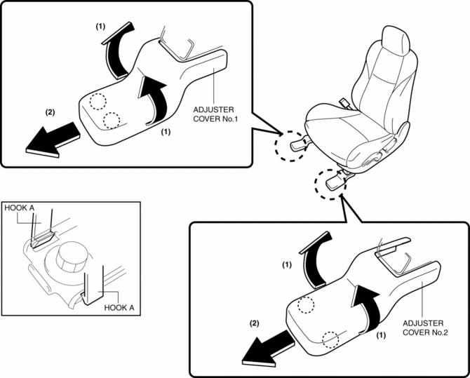
4. Detach hook A while pulling the adjuster cover No.1 and No.2 in the direction of the arrow (1), and remove it in the direction of arrow (2) shown in the figure.
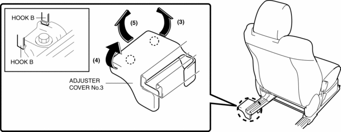
5. Detach hook B while pulling the adjuster cover No.3 in the direction of the arrow (3), (4) and remove it in the direction of arrow (5) shown in the figure.
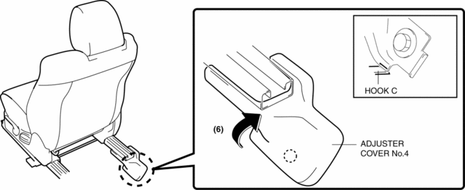
6. Pull up the adjuster cover No.4 in the direction of arrow (6) shown in the figure, while remove the hook C.
7. Remove the front cover.(Vehicles with power seat system).
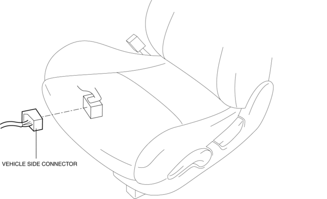
8. Disconnect the connector.
9. Remove the bolts, then remove the front seat.
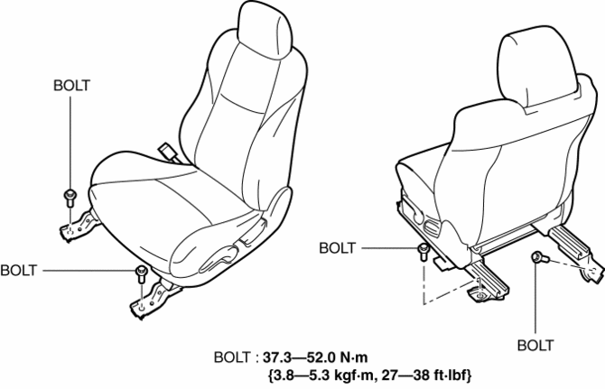
10. Install in the reverse order of removal.
Vehicles with power seat system
1. Switch the ignition to off.
2. Remove the battery cover..
3. Disconnect the negative battery cable and wait 1 min or more
..
4. Detach hook A while pulling the adjuster cover No.1 and No.2 in the direction of the arrow (1), and remove it in the direction of arrow (2) shown in the figure.
5. Detach hook B while pulling the adjuster cover No.3 in the direction of the arrow (3), (4) and remove it in the direction of arrow (5) shown in the figure.
6. Pull up the adjuster cover No.4 in the direction of arrow (6) shown in the figure, while remove the hook C.
7. Remove the front cover.(Vehicles with power seat system).
8. Remove the bolts, then remove the front seat.
9. Disconnect the connector.
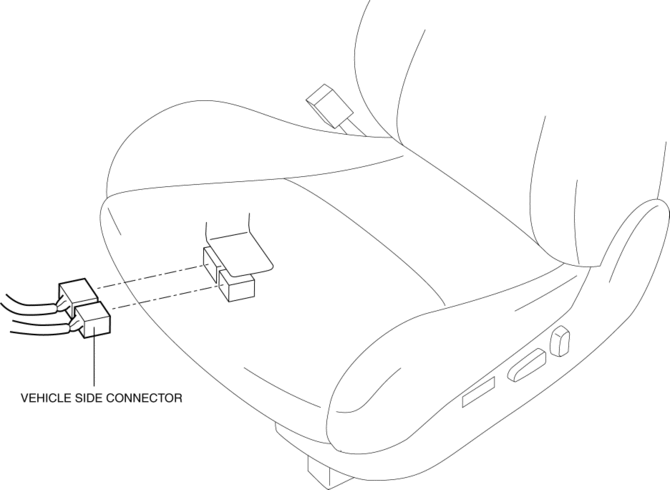
10. Install in the reverse order of removal.
Passenger-side
1. Switch the ignition to off.
2. Remove the battery cover..
3. Disconnect the negative battery cable and wait 1 min or more
..
4. Remove the belt anchor cover..
5. Remove the lower anchor of the front seat belt installation bolt..
6. Detach hook A and B while pulling the adjuster cover No.1 in the direction of the arrow (1), (2) and remove it in the direction of arrow (3) shown in the figure.
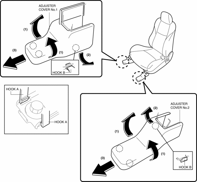
7. Detach hook C while pulling the adjuster cover No.3 in the direction of the arrow (4) and remove it in the direction of arrow (5) shown in the figure, while remove the tab D, F and hook E.
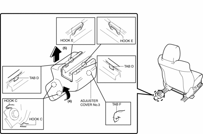
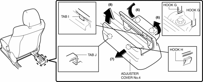
8. Detach hook G and H while pulling the adjuster cover No.4 in the direction of the arrow (6), (7) and remove it in the direction of arrow (8) shown in the figure, while remove the tab I and J.
CAUTION:
-
When pulling the adjuster cover No.4, be careful not to damage the hooks and tabs.
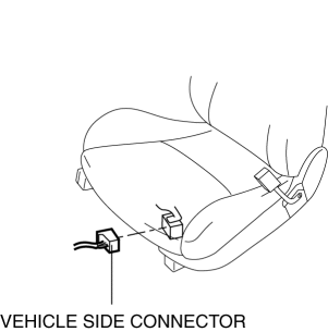
9. Disconnect the connector.
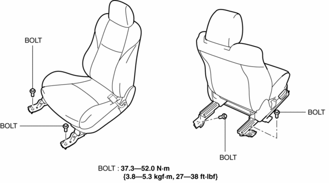
10. Remove the bolts, then remove the front seat.
11. Install in the reverse order of removal.
 Front Seat Rail Guide Cover Removal/Installation
WARNING:
Handling a front seat (with built-in side air bag) improperly can accidentally
operate (deploy) the air bag, which may seriously injure you. Read the service
warnings before han ...
 Front Seat Slide Adjuster Removal/Installation
WARNING:
Handling the front seats improperly can accidentally deploy the side air
bag, which may seriously injure you. Read air bag system service warnings and
cautions before handling t ...
Other materials:
Oil Pump Removal/Installation [Mzr 2.3 Disi Turbo]
WARNING:
Hot engines and engine oil can cause severe burns. Turn off the engine and
wait until it and the engine oil have cooled.
A vehicle that is lifted but not securely supported on safety stands is dangerous.
It can slip or fall, causing death or serious injury. Never work ...
Thermostat Removal/Installation [Mzr 2.0, Mzr 2.5]
WARNING:
Never remove the cooling system cap or loosen the radiator drain plug while
the engine is running, or when the engine and radiator are hot. Scalding engine
coolant and steam may shoot out and cause serious injury. It may also damage
the engine and cooling system.
Tu ...
Key Interlock System Inspection
Key Interlock System Inspection
1. Switch the ignition to ON.
2. Perform the following procedures to inspect the key interlock system.
If there is any malfunction, inspect the key interlock solenoid and NOT P
position switch..
a. Verify that the ignition cannot be switched to off ...
