Mazda 3 Service Manual: Hazard Warning Switch Inspection
1. Disconnect the negative battery cable..
2. Remove the center panel..
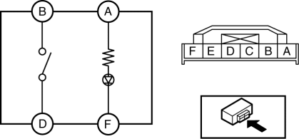
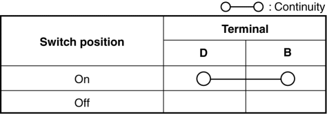
3. Verify that the continuity between the hazard switch terminals is as indicated in the table.

-
If not as indicated in the table, replace the hazard warning switch.

4. Apply battery voltage to hazard switch terminal A, and connect terminal F to ground.
5. Verify that the LED illuminates.
-
If there is any malfunction, replace the hazard warning switch.
 Front Fog Light Switch Inspection
1. Disconnect the negative battery cable..
2. Remove the column cover..
3. Remove the light switch..
4. Verify that the continuity between the front fog light switch terminals is
as indicated ...
 Hazard Warning Switch Removal/Installation
1. Disconnect the negative battery cable..
2. Remove the center panel..
3. Remove in the order indicated in the table.
1
Screw
2
Hazard wa ...
Other materials:
Steering Switch Removal/Installation
WARNING:
Handling the air bag module improperly can accidentally deploy the air bag
module, which may seriously injure you. Read the air bag system service warnings
and cautions before handling the air bag module..
1. Disconnect the negative battery cable and wait for 1 min or mo ...
Engine Coolant Leakage Inspection [Mzr 2.0, Mzr 2.5]
WARNING:
Never remove the cooling system cap or loosen the radiator drain plug while
the engine is running, or when the engine and radiator are hot. Scalding engine
coolant and steam may shoot out and cause serious injury. It may also damage
the engine and cooling system.
Tu ...
Interior Equipment (View A)
Door-lock knob
Turn and lane-change signal
Lighting control
Wiper and washer lever
DSC OFF switch
Tire pressure monitoring system set switch
LDWS switch
AFS OFF switch
BSM OFF switch
Headlight leveling switch
Outside mirror switch
Door-lock switch
Power window lock s ...
