Mazda 3 Service Manual: Clutch Master Cylinder Removal/Installation [C66 M R]
CAUTION:
-
Secure the steering wheel using tape or a cable to prevent the steering shaft from rotating after disconnecting the steering shaft. If the steering wheel rotates after the steering shaft and the steering gear and linkage are disconnected, the internal parts of the clock spring could be damaged.
-
Do not allow clutch fluid get on a painted surface. Clutch fluid contains properties which can dissolve the paint. If clutch fluid gets on a painted surface, wash it off with water immediately and wipe the area off completely.
1. Remove the battery cover..
2. Disconnect the negative battery cable..
3. Remove the battery component. (ex: battery, battery tray and PCM component).
4. Remove the front scuff plate (LH)..
5. Remove the front side trim (LH)..
6. Remove the upper panel..
7. Remove the shift knob..
8. Remove the shift panel..
9. Remove the side wall..
10. Remove the console..
11. Set the hood release lever out of the way..
12. Remove the lower panel. (driver-side).
13. Remove the starter cut relay. (with advanced keyless entry and push button start system).
14. Remove the BCM..
15. Remove the clutch pedal position switch..
16. Remove the starter interlock switch..
17. Remove the joint cover..
18. Disconnect the steering shaft from steering gear..
19. Disconnect the clutch pipe and hose No.1 from clutch master cylinder, and plug it to avoid clutch fluid leakage..
20. Disconnect the clutch reserve hose from clutch master cylinder, and plug it to avoid clutch fluid leakage..
21. Remove the clutch pedal installation nuts.
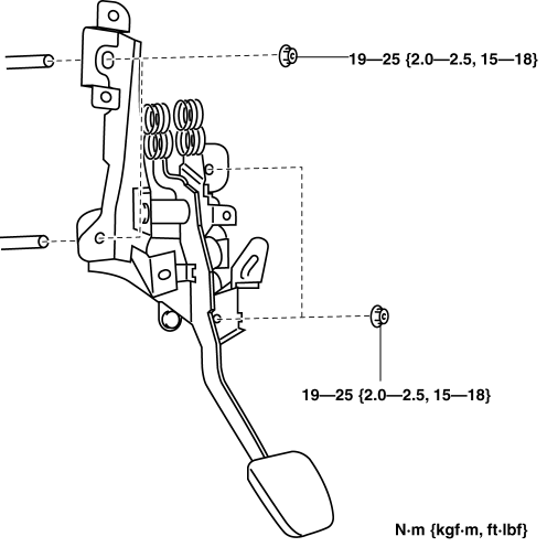
22. Remove the clutch master cylinder.
a. Disconnect the clutch master cylinder (rubber) from the body.
b. Rotate the clutch master cylinder in the direction of the arrow shown in the figure to disconnect the clutch master cylinder (body) and clutch pedal.
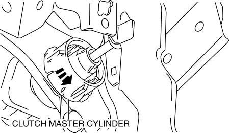
c. Disengage the tabs of the push rod and remove the master cylinder using a flathead screwdriver.
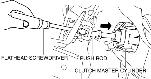
23. Install the clutch master cylinder.
a. Insert the clutch master cylinder into the installation hole of the body.
b. Insert the stud bolt into the installation hole of the clutch pedal.
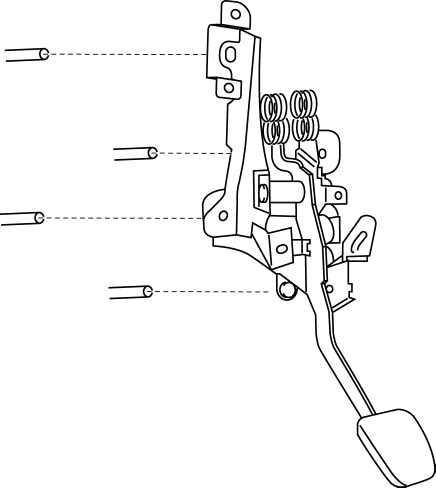
c. Engage the tabs of the push rod with the clutch pedal as shown in the figure.
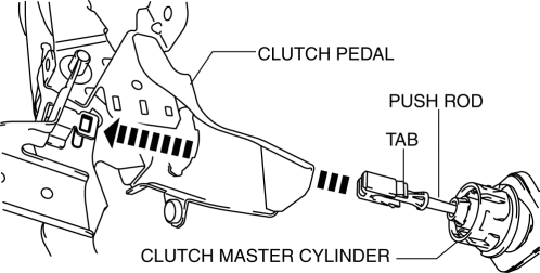
d. Rotate the clutch master cylinder in the direction shown until it stops.
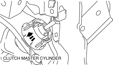
e. Install the clutch master cylinder (rubber) to the body.
24. Connect the clutch reserve hose to clutch master cylinder..
25. Connect the clutch pipe and hose No.1 to clutch master cylinder..
26. Connect the steering shaft..
27. Install the joint cover..
28. Install the BCM..
29. Install the starter cut relay. (with advanced keyless entry and push button start system).
30. Install the lower panel. (driver-side).
31. Install the hood release lever..
32. Install the console..
33. Install the side wall..
34. Install the shift panel..
35. Install the shift knob..
36. Install the upper panel..
37. Install the front side trim (LH)..
38. Install the front scuff plate (LH)..
39. Bleed the air from the clutch system..
40. Inspect the clutch pedal..
41. Install a new starter interlock switch..
42. Install a new clutch pedal position switch..
43. Install the battery component. (ex: battery, battery tray and PCM component).
44. Connect the negative battery cable..
45. Install the battery cover..
46. Fully depress the clutch pedal, and verify that the engine starts.
 Clutch Fluid Replacement/Air Bleeding [C66 M R]
CAUTION:
Do not allow clutch fluid get on a painted surface. Clutch fluid contains
properties which can dissolve the paint. If clutch fluid gets on a painted surface,
wash it off with wa ...
 Clutch Pedal Inspection [C66 M R]
NOTE:
For the clutch pedal inspection, note the followings and measure each inspection
location.
Measure the center of the upper surface of the pedal pad for each inspection.
...
Other materials:
No.28 Fuel Filling Shut Off Concerns [Mzr 2.0, Mzr 2.5]
28
FUEL FILLING SHUT OFF CONCERNS
DESCRIPTION
Fuel does not shut off properly.
POSSIBLE CAUSE
PCM DTC is stored
Nonreturn valve malfunction
Fuel nozzle ...
Front Crossmember Removal/Installation
CAUTION:
Performing the following procedures without first removing the ABS wheel-speed
sensor may possibly cause an open circuit in the wiring harness if it is pulled
by mistake. Before performing the following procedures, disconnect the ABS wheel-speed
sensor wiring harness connec ...
Fuel Injector Inspection [Mzr 2.0, Mzr 2.5]
Resistance Inspection
1. Remove the battery cover..
2. Disconnect the negative battery cable..
3. Disconnect the fuel injector connector.
4. Inspect the resistance between fuel injector terminals A and B.
Fuel injector resistance
11.4—12.6 ohms [20 °C {68 °F}]
If not ...
