Mazda 3 Service Manual: Clutch Pedal Inspection [C66 M R]
NOTE:
-
For the clutch pedal inspection, note the followings and measure each inspection location.
-
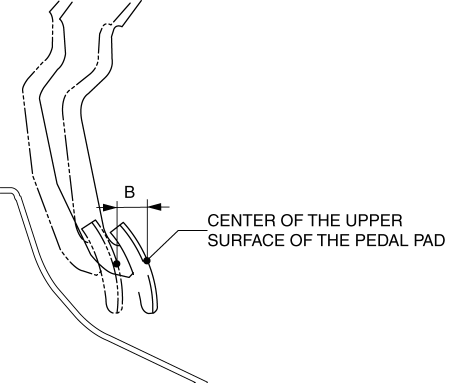
Measure the center of the upper surface of the pedal pad for each inspection.
-
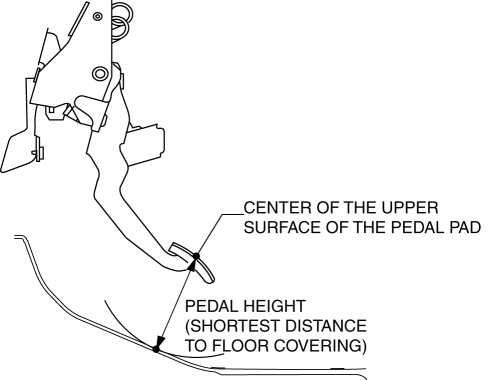
If the distance from the pedal pad to the floor covering is measured, measure the shortest distance from the center of the upper surface of the pedal pad to the floor covering.
Pedal Inspection Preparation
1. Verify that there is no malfunction in the clutch fluid level..
2. Verify that there is no clutch fluid leakage..
Pedal Height Inspection
1. Perform “Pedal Inspection Preparation”..
2. Measure the pedal height with the clutch pedal released as shown in the figure.
-
Pedal height (reference value)
-
142.8 mm {5.622 in}
-
If it is not the specification, replace the clutch pedal..
Pedal Free Play Inspection
1. Perform “Pedal Inspection Preparation”..
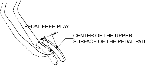
2. Depress the clutch pedal by hand until clutch resistance is felt, and measure the pedal free play as shown in the figure.
-
Pedal free play (reference value)
-
15 mm {0.59 in} or less
-
If it exceeds the specification, replace the clutch pedal..
Pedal Full Stroke Inspection
1. Perform “Pedal Inspection Preparation”..
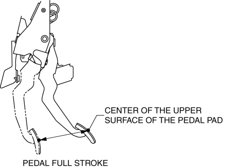
2. Depress the clutch pedal from the released condition to the full depression position, and measure the pedal full stroke as shown in the figure.
-
Pedal full stroke (reference value)
-
140 mm {5.51 in}
-
If it is not the specification, replace the clutch pedal..
Clutch Disengagement Point Inspection
WARNING:
-
When performing the following procedure, make sure that the area around the vehicle is free of people or objects as the vehicle might move suddenly.
NOTE:
-
There are two methods for the clutch disengagement point inspection as follows: Perform any of the following inspection procedures for the clutch disengagement point inspection.
-
Procedure A: Procedure for measuring the distance from the clutch disengagement point to the floor.
-
Procedure B: Procedure for measuring the distance from the clutch disengagement point to the maximum clutch pedal depression position.
Procedure A
1. Perform “Pedal Inspection Preparation”..
2. Verify that the pedal height is normal..
3. Verify that the pedal free play is normal..
4. Verify that the pedal full stroke is normal..
5. Apply the parking brake and fix the front and rear of the wheels with the wheel chocks.
6. Start the engine.
7. With the clutch pedal depressed, move the shift lever to the position just before engaging the reverse gear. (Do not shift completely to reverse position)
8. Gradually release the clutch pedal and then hold it at the point where the sound of gear-grinding begins (clutch disengagement point).
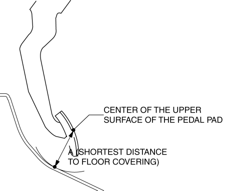
9. Measure distance A as shown in the figure when the clutch pedal is at the clutch disengagement point.
-
Distance A (reference value)
-
52.3 mm {2.06 in} or more
-
If it is less than the specification, bleed the air from the clutch system..
Procedure B
1. Perform “Pedal Inspection Preparation”..
2. Verify that the pedal height is normal..
3. Verify that the pedal free play is normal..
4. Verify that the pedal full stroke is normal..
5. Apply the parking brake and fix the front and rear of the wheels with the wheel chocks.
6. Start the engine.
7. With the clutch pedal depressed, move the shift lever to the position just before engaging the reverse gear. (Do not shift completely to reverse position)
8. Gradually release the clutch pedal and then hold it at the point where the sound of gear-grinding begins (clutch disengagement point).
9. Depress the clutch pedal from the clutch disengagement point to the full depression position, and measure distance B as shown in the figure.
-
Distance B (reference value)
-
12.5 mm {0.492 in} or more
-
If it is less than the specification, bleed the air from the clutch system..
 Clutch Master Cylinder Removal/Installation [C66 M R]
CAUTION:
Secure the steering wheel using tape or a cable to prevent the steering shaft
from rotating after disconnecting the steering shaft. If the steering wheel
rotates after the steer ...
 Clutch Pedal Position (CPP) Switch Inspection [Mzr 2.0, Mzr 2.5]
Continuity Inspection
1. Verify that the CPP switch is installed properly..
2. Remove the battery cover..
3. Disconnect the negative battery cable..
4. Disconnect the CPP switch connector..
5 ...
Other materials:
Recliner Motor Inspection
1. Remove the battery cover..
2. Disconnect the negative battery cable and wait 1 min or more..
3. Disconnect the recliner motor connector.
4. Apply battery positive voltage to the recliner motor terminals and inspect
the recliner motor operation.
If not as specified, replace the ...
Front Wheel Hub Bolt Replacement
1. Remove the brake calliper component and disc plate..
2. Remove the wheel hub bolt using the SST as shown in the figure.
NOTE:
When removing the wheel hub bolts, perform the work between range A shown
in the figure to assure a space for the bolt removal.
3. Place a new whe ...
Front Door Hinge Removal/Installation
1. Disconnect the negative battery cable..
2. Remove the following parts:
a. Front bumper.
b. Front combination light.
c. Front fender molding.
d. Side step molding.
e. Front fender panel.
f. Front door.
3. Remove in the order indicated in the table.
1
B ...
