
Mazda 3 Service Manual: Liftgate Adjustment
1. Measure the gap and height difference between the liftgate and the body.
2. Loosen the liftgate hinge installation bolts and adjust the gap by moving the liftgate.
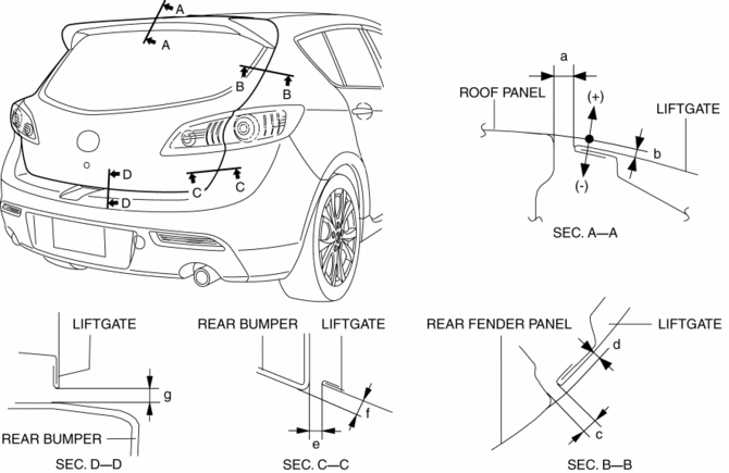
-
Standard clearance
-
a: 5.0―7.0 mm {0.20―0.27 in}
-
b: -2.0―0 mm {-0.078―0 in}
-
c: 3.0―6.0 mm {0.12―0.23 in}
-
d: -1.4―1.6 mm {-0.055―0.062 in}
-
e: 2.5―6.5 mm {0.10―0.25 in}
-
f: -0.9―3.0 mm {-0.03―0.11 in}
-
g: 4.0―8.0 mm {0.16―0.31 in}
3. Tighten the bolts.
 Hood Removal/Installation
WARNING:
Removing the hood without supporting it could cause the hood to fall and
cause serious injury. Always perform the procedure with at least another person
to prevent the hood from ...
 Liftgate Hinge Removal/Installation
1. Disconnect the negative battery cable..
2. Remove the following parts:
a. Rear scuff plate.
b. Rear seat cushion.
c. Rear seat back.
d. Lower anchor installation bolts on the rear seat be ...
Other materials:
Power Window Lock Switch
This feature prevents all power windows
from operating, except the driver's power
window. Keep this switch in the locked
position while children are in the vehicle.
Locked position (button depressed):
Only the driver's power window can be
operated.
Unlocked position (button not
depressed ...
Antenna Feeder No.4 Removal/Installation
Removal
NOTE:
The antenna feeder No.4 is integrated with the dashboard wiring harness.
1. Refer to DASHBOARD DISASSEMBLY/ASSEMBLY.
Installation
CAUTION:
If the antenna feeder No.4 is installed with tension on the cable and wiring
harness it could result in loosening of t ...
Front Seat Cushion Trim Removal/Installation
WARNING:
Handling a front seat (with built-in side air bag) improperly can accidentally
operate (deploy) the air bag, which may seriously injure you. Read the service
warnings before handling a front seat (with built-in side air bag)..
CAUTION:
After removing a front seat ...
