
Mazda 3 Service Manual: Shift Lock System Inspection
Shift-Lock System Inspection
1. Switch the ignition to ON.
2. Shift the selector lever to the P position.
3. Perform the following procedures to inspect the shift-lock system.
-
If there is any malfunction, inspect the shift-lock solenoid and P position switch..
a. Verify that the selector lever cannot be shifted from P to R position when the brake pedal is released.
b. Verify that the selector lever can be shifted from P to R position when the brake pedal is depressed.
Shift-Lock Solenoid and P Position Switch Inspection
1. Perform the following procedures.
a. Remove the battery cover..
b. Disconnect the negative battery cable..
c. Remove the console..
d. Disconnect the selector lever component connector.
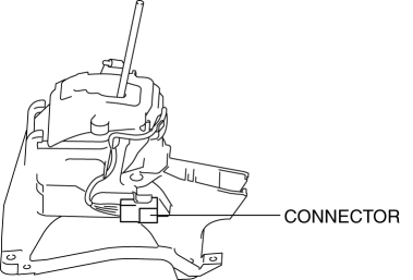
2. Measure the voltage between the selector lever component terminals.
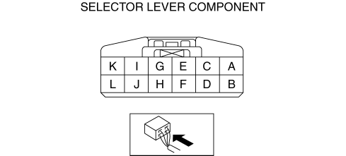
-
If there is any malfunction, repair or replace the related wiring harness.
-
If there is no malfunction even though the shift-lock system has any malfunction, replace the selector lever component..
|
Terminals |
Connected to |
Test condition |
Voltage (V) |
|
E—GND |
Brake switch |
Brake pedal released |
Below 1.0 |
|
Brake pedal depressed |
B+ |
||
|
I—GND |
Ignition switch |
Switch the ignition to off |
Below 1.0 |
|
Switch the ignition to ACC or ON |
B+ |
||
|
K—GND |
GND |
Under any condition |
Below 1.0 |
Emergency Override Button Inspection
1. Switch the ignition to off.
2. Verify that the selector lever is in the P position.
3. Without the brake pedal depressed, verify that the selector lever cannot be shifted from the P position.
4. Remove the cover using a tape-wrapped flathead screwdriver.
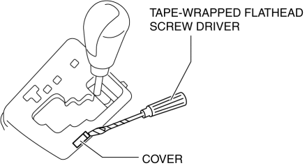
5. Insert the flathead screwdriver into the emergency override hole and push it down.
6. Verify that the selector lever can be shifted from the P position.
-
If there is any malfunction, replace the selector lever component..
 Selector Lever Inspection
1. Switch the ignition to ON.
2. Perform the following procedures to inspect the selector lever.
If there is any malfunction, adjust the selector cable..
a. Verify that the selector le ...
 Solenoid Valve Inspection [FS5 A EL]
CAUTION:
Water or foreign objects entering the connector can cause a poor connection
or corrosion. Be sure not to drop water or foreign objects on the connector
when disconnecting it.
...
Other materials:
Steering Gear And Linkage Assembly
CAUTION:
To prevent damage to the steering gear, secure it to the vise using a copper
plate or clean cloth.
1. Assemble in the order indicated in the table.
1
Gear housing
2
Mounting rubber
(See Mounting Rubber Assembly No ...
Power Outer Mirror Switch Inspection
1. Disconnect the negative battery cable..
2. Remove the following parts:
a. Inner garnish.
b. Front door trim.
c. Switch panel.
3. Verify that the continuity between the power outer mirror switch terminals
is as indicated in the table.
If not as indicated in the table, replace t ...
Front Power Window Regulator Removal/Installation
1. To access the glass installation bolt, position the front door glass so that
the distance from the top of the front door glass to the upper part of the front
beltline molding is approx. 80 mm {3.1 in}.
2. Disconnect the negative battery cable..
3. Remove the following parts:
a. Inne ...
