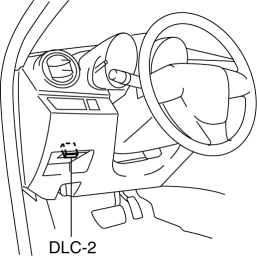
Mazda 3 Service Manual: Active Command Modes Inspection [Instrument Cluster]
1. Connect the M-MDS (IDS) to the DLC-2.

2. After the vehicle is identified, select the following items from the initialization screen of the IDS.
a. Select “DataLogger”.
b. Select “Modules”.
c. Select “IC”.
3. Select the simulation items from the PID table.
4. Perform the active command modes function, inspect the operations for each parts.
-
If the operation of output parts cannot be verified after the active command mode inspection is performed, this could indicate the possibility of an open or short circuit, sticking, or operation malfunction in the output parts.
 Clock Spring Adjustment
NOTE:
The adjustment procedure is also specified on the caution label of the clock
spring.
1. Set the front wheels straight ahead.
CAUTION:
The clock spring will break if ov ...
Other materials:
Radiator Drain Plug Replacement [Mzr 2.0, Mzr 2.5]
WARNING:
Never remove the cooling system cap or loosen the radiator drain plug while
the engine is running, or when the engine and radiator are hot. Scalding engine
coolant and steam may shoot out and cause serious injury. It may also damage
the engine and cooling system.
Tu ...
Key Reminder Switch Inspection
1. Disconnect the negative battery cable. (See BATTERY REMOVAL/INSTALLATION [MZR
2.0, MZR 2.5].)(See BATTERY REMOVAL/INSTALLATION [MZR 2.3 DISI Turbo].)(See BATTERY
REMOVAL/INSTALLATION [SKYACTIV-G 2.0].)
2. Remove the column cover. (See COLUMN COVER REMOVAL/INSTALLATION.)
3. Disconnect the ...
Combination Switch Disassembly/Assembly
CAUTION:
Handling the air bag module improperly can accidentally deploy the air bag
module, which may seriously injure you. Read the air bag system service warnings
and cautions before handling the air bag module..
1. Switch the ignition to off.
2. Disconnect the negative batte ...

