Mazda 3 Service Manual: Control Valve Body Removal/Installation [FS5 A EL]
Primary Control Valve Body On-Vehicle Removal
WARNING:
-
A hot transaxle and ATF can cause severe burns. Turn off the engine and wait until they are cool.
-
Using compressed air can cause dirt and other particles to fly out, causing injury to the eyes. Wear protective eyeglasses whenever using compressed air.
1. Remove the battery cover..
2. Disconnect the negative battery cable.
3. Remove the aerodynamic under cover NO.2..
4. Clean the transaxle exterior throughout with a steam cleaner or cleaning solvents.
5. Drain the ATF..
6. Remove the oil pan.
7. Remove the oil strainer.
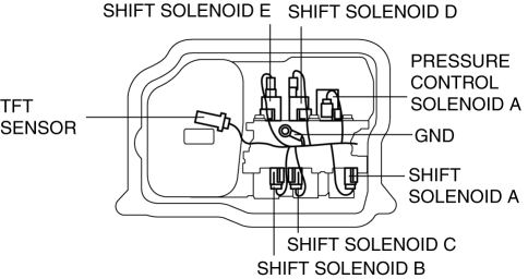
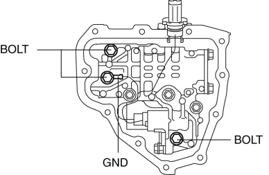
8. Disconnect each solenoid valve connector and GND.
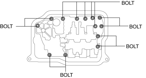
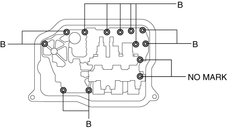
9. Remove the bolts as shown, then remove the primary control valve body.
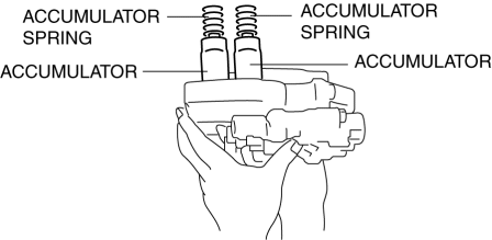
10. Remove the accumulators and accumulator springs.
Primary Control Valve Body On-Vehicle Installation
CAUTION:
-
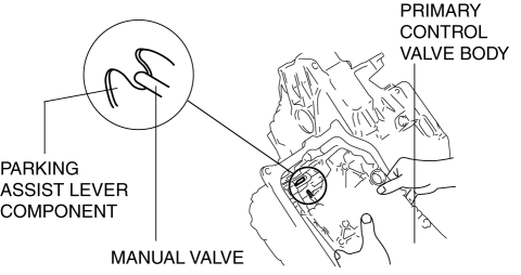
Be sure to align the parking rod and the manual valve.
1. Install the accumulator springs, accumulators and primary control valve body.
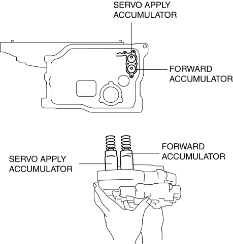
Accumulator spring specification
|
Spring |
Outer diameter (mm {in}) |
Free Length (mm {in}) |
No. of coils |
Wire diameter (mm {in}) |
|
Servo apply accumulator large spring |
21.0 {0.827} |
67.8 {2.669} |
10.3 |
3.5 {0.138} |
|
Servo apply accumulator small spring |
13.0 {0.512} |
67.8 {2.669} |
17.1 |
2.2 {0.087} |
|
Forward accumulator large spring |
21.0 {0.827} |
75.0 {2.953} |
10.7 |
2.3 {0.091} |
|
Forward accumulator small spring |
15.6 {0.614} |
49.0 {1.929} |
7.7 |
2.4 {0.094} |
2. Tighten the bolts as shown to install the primary control valve body.
-
Tightening torque
-
8—10 N·m {82—101 kgf·cm, 71—88 in·lbf}
|
Mark |
Length measured from below the head |
|
B |
40mm {1.575 in} |
|
No mark |
70mm {2.756 in} |
3. Match the harness colors, then connect each solenoid valves connector. Connector color (harness-side)
|
Solenoid valve |
Connector color |
|
Pressure control solenoid A |
Black |
|
Shift solenoid A |
White |
|
Shift solenoid B |
Blue |
|
Shift solenoid C |
Green |
|
Shift solenoid D |
White |
|
Shift solenoid E |
Black |
4. Install the GND.
-
Tightening torque
-
8—10 N·m {82—101 kgf·cm, 71—88 in·lbf}
5. Install the oil strainer.
6. Install the TFT sensor to the oil strainer.
7. Apply a light coat of silicon sealant (TB1217E) to the contact surfaces of the oil pan and transaxle case.
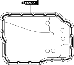
CAUTION:
-
If any sealant remains on the sealing surfaces of the transaxle case and oil pan, transaxle damage may occur. Use a cleaning fluid to remove any old sealant from the transaxle case and oil pan.
8. Install the oil pan before the applied sealant starts to harden.
-
Tightening torque
-
6—8 N·m {62—81 kgf·cm, 54—70 in·lbf}
9. Add the ATF..
10. Install the aerodynamic under cover NO.2..
11. Connect the negative battery cable.
12. Install the battery cover..
13. Perform the “Mechanical System Test”..
14. Perform the “Road Test”..
Secondary Control Valve Body On-Vehicle Removal
WARNING:
-
A hot transaxle and ATF can cause severe burns. Turn off the engine and wait until they are cool.
-
Using compressed air can cause dirt and other particles to fly out, causing injury to the eyes. Wear protective eyeglasses whenever using compressed air.
1. Remove the battery cover..
2. Disconnect the negative battery cable.
3. Remove the battery component (ex: battery, battery tray and PCM component)..
4. Remove the aerodynamic under cover NO.2..
5. Clean the transaxle exterior throughout with a steam cleaner or cleaning solvents.
6. Drain the ATF..
7. Remove the oil cover.
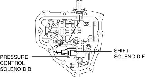
8. Disconnect each solenoid valve connector.

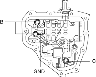
9. Remove the bolts and GND as shown, then remove the secondary control valve body.
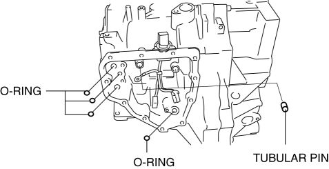
10. Remove the tubular pin and O-ring.
Secondary Control Valve Body On-Vehicle Installation
1. Install the tubular pin and new O-rings to the transaxle case.
2. Install the secondary control valve body.
3. Tighten the bolts and GND as shown to install the secondary control valve body.
-
Tightening torque
-
8—10 N·m {82—101 kgf·cm, 71—88 in·lbf}
|
Mark |
Length measured from below the head |
|
B |
40mm {1.575 in} |
|
C |
50mm {1.967 in} |
4. Connect each solenoid valve connector.
Connector color (harness-side)
|
Solenoid valve |
Connector color |
|
Pressure control solenoid B |
White |
|
Shift solenoid F |
Black |
5. Apply a light coat of silicon sealant (TB1217E) to the contact surfaces of the oil cover and transaxle case.
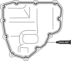
CAUTION:
-
If any sealant remains on the sealing surfaces of the transaxle case and oil cover, transaxle damage may occur. Use a cleaning fluid to remove any old sealant from the transaxle case and oil cover.
6. Install the oil cover before the applied sealant starts to harden.
-
Tightening torque
-
8—10 N·m {82—101 kgf·cm, 71—88 in·lbf}
7. Add the ATF..
8. Install the aerodynamic under cover NO.2..
9. Install the battery component (ex: battery, battery tray and PCM component)..
10. Connect the negative battery cable.
11. Install the battery cover..
12. Perform the “Mechanical System Test”..
13. Perform the “Road Test”..
 Basic Inspection [FS5 A EL]
STEP
INSPECTION
ACTION
1
Measure the battery voltage.
Is the battery voltage 10.0—14.0 V?
Yes
Go to ...
 Control Valve Body Removal/Installation [Fw6 A EL]
On-Vehicle Removal
WARNING:
A hot transaxle and ATF can cause severe burns. Turn off the engine and wait
until they are cool.
Using compressed air can cause dirt and other particle ...
Other materials:
Front Scuff Plate Removal/Installation
1. Detach tab A while pulling the front scuff plate in the direction of the arrow
(1) shown in the figure, then detach hook B, clips C, and pins D while pulling in
the direction of the arrow (2).
2. Detach tab E while pulling the front scuff plate in the direction of the arrow
(3) shown in t ...
Fuel Pump Control Module Inspection [Skyactiv G 2.0]
1. Perform the KOEO self-test..
2. Verify that a fuel pump control module related DTC is detected..
If DTCs are detected, repair the malfunctioning part according to the applicable
DTC troubleshooting..
If a DTC is not detected, go to the next step.
3. Inspect the followin ...
Bluetooth® Audio (Type A)
Applicable Bluetooth ® specification
(Recommended)
Ver. 2.0
Response profile
A2DP (Advanced Audio Distribution
Profile) Ver. 1.0/1.2
AVRCP (Audio/Video Remote Control
Profile) Ver. 1.0/1.3
A2DP is a profile which transmits only
audio to the Bluetooth ® unit. If your
Bluetooth ® ...
