
Mazda 3 Service Manual: Liftgate Latch Switch Inspection
1. Disconnect the negative battery cable..
2. Remove the following parts:
a. Liftgate upper trim.
b. Liftgate side trim.
c. Liftgate lower trim.
d. Liftgate latch and lock actuator.
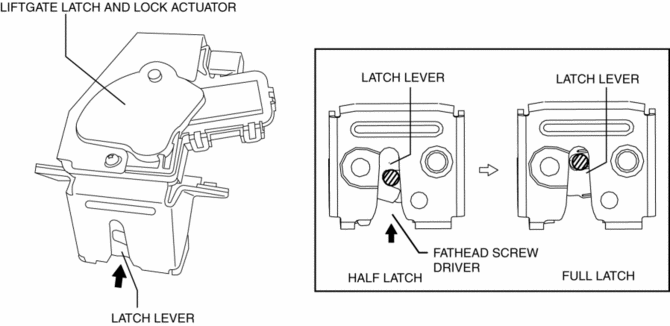
3. Press the latch in using a flathead screwdriver to inspect the latch lever condition.
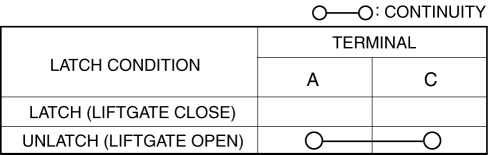
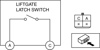
4. Verify that the continuity is as indicated in the table.
-
If not as indicated in the table, replace the liftgate latch and lock actuator
 Liftgate Latch And Lock Actuator Removal/Installation
1. Disconnect the negative battery cable..
2. Remove the following parts:
a. Liftgate upper trim.
b. Liftgate side trim.
c. Liftgate lower trim.
3. Disconnect the connector.
4. Remove ...
 Liftgate Lock Striker Removal/Installation
1. Remove the trunk end trim..
2. Remove the bolts, then remove the liftgate lock striker.
3. Install in the reverse order of removal.
4. Adjust the liftgate lock striker.. ...
Other materials:
Replacing Windshield Wiper Blades
When the wipers no longer clean well, the
blades are probably worn or cracked.
Replace them.
CAUTION
To prevent damage to the wiper arms
and other components, do not try to
sweep the wiper arm by hand.
NOTE
When raising both windshield wiper arms,
raise the driver's side ...
Air Bypass Valve Inspection [Mzr 2.3 Disi Turbo]
1. Remove the air bypass valve..
2. Connect the vacuum pump to the vacuum ports of the air bypass valve.
3. Verify that the airflow is as indicated in the table.
Vacuum
(kPa {mmHg, inHg})
Valve operation condition
Airflow between port A—B
...
Manual Shift Mode
The manual shift mode gives you the feel
of driving a manual transaxle vehicle by
allowing you to operate the selector lever
manually. This allows you to control
engine rpm and torque to the drive wheels
much like a manual transaxle when more
control is desired.
To change to manual shift mo ...
