Mazda 3 Service Manual: On Board Diagnostic System Simulation Inspection [Fw6 A EL]
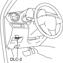
1. Connect the M-MDS (IDS) to the DLC-2.
2. After the vehicle is identified, select the following items from the initialization screen of the IDS.
a. Select “DataLogger”.
b. Select “Modules”.
c. Select “TCM”.
3. Select the simulation items from the PID table.
4. Perform the active command modes function, inspect the operations for each parts.
-
If the operation of output parts cannot be verified after the active command mode inspection is performed, this could indicate the possibility of an open or short circuit, sticking, or operation malfunction in the output parts.
|
Item |
Description |
Unit/Condition |
Operation condition |
|
SS_ON-OFF |
On/off solenoid condition |
Off/On |
Under the following conditions:
|
|
SS1_C |
Shift solenoid No.1 target current |
A |
Under the following conditions:
|
|
SS2_C |
Shift solenoid No.2 target current |
A |
Under the following conditions:
|
|
SS3_C |
Shift solenoid No.3 target current |
A |
Under the following conditions:
|
|
SS4_C |
Shift solenoid No.4 target current |
A |
Under the following conditions:
|
|
SSLU_C |
TCC control solenoid target current |
A |
Under the following conditions:
|
|
SSP_C |
Pressure control solenoid target current |
A |
Idling at P or N position |
 On Board Diagnostic System Simulation Inspection [FS5 A EL]
1. Connect the M-MDS(IDS) to the DLC-2.
2. After the vehicle is identified, select the following items from the initialization
screen of the IDS.
a. Select "DataLogger".
b. Selec ...
 PID/Data Monitor Inspection [Bcm]
1. Connect the M-MDS (IDS) to the DLC-2.
2. After the vehicle is identified, select the following items from the initialization
screen of the IDS.
a. Select “DataLogger”.
b. Select “ ...
Other materials:
Rear Cross Traffic Alert (RCTA)
The Rear Cross Traffic Alert (RCTA) system is designed to assist the driver
in checking the
area to the rear of the vehicle on both sides while the vehicle is reversing by
alerting the
driver to the presence of vehicles approaching the rear of the vehicle.
The Rear Cross Traffic Alert (RCTA ...
Schedule 2
U.S.A. (severe driving conditions) and Puerto Rico residents
Chart symbols:
I: Inspect: Inspect and clean, repair, adjust, fill up, or replace if
necessary.
R: Replace
L : Lubricate
T: Tighten
Remarks:
*1 Engine oil flexible maintenance is available for U.S.A. and Puerto Rico
resi ...
Car Navigation Unit Removal/Installation
With Audio Unit (Without Display)
NOTE:
Car-navigation unit is integrated with the multi information display.
1. Refer to MULTI INFORMATION DISPLAY REMOVAL/INSTALLATION.
With Audio Unit (With Display)
1. Disconnect the negative battery cable..
2. Remove the following parts:
a. ...
