Mazda 3 Service Manual: PID/Data Monitor Inspection [Standard Deployment Control System]
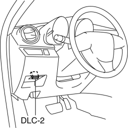
1. Connect the M-MDS (IDS) to the DLC-2.

2. After the vehicle is identified, select the following items from the initialization screen of the IDS.
a. Select “DataLogger”.
b. Select “Modules”.
c. Select “RCM”.
3. Select the applicable PID from the PID table.
4. Verify the PID data according to the directions on the screen.
NOTE:
-
The PID data screen function is used for monitoring the calculated value of input/output signals in the module. Therefore, if the monitored value of the output parts is not within the specification, it is necessary to inspect the monitored value of input parts corresponding to the applicable output part control. In addition, because the system does not display an output part malfunction as an abnormality in the monitored value, it is necessary to inspect the output parts individually.
 PCM Removal/Installation [Mzr 2.0, Mzr 2.5]
1. Remove the battery cover..
2. Disconnect the negative battery cable..
3. Remove the following items:.
Battery
PCM cover No.1
4. Disconnect the PCM connector..
5. Remove ...
 PID/Data Monitor Inspection [Two Step Deployment Control System]
1. Connect the M-MDS (IDS) to the DLC-2.
2. After the vehicle is identified, select the following items from the initialization
screen of the IDS.
a. Select “DataLogger”.
b. Select “Module ...
Other materials:
Keyless Antenna Removal/Installation
Interior, Front
1. Disconnect the negative battery cable..
2. Remove the following parts:
a. Upper panel.
b. Shift knob (MTX).
c. Selector lever knob (ATX).
d. Shift panel.
e. Side wall.
f. Center panel.
g. Audio unit.
h. Rear heat duct (1).
3. Disconnect the connector.
4. ...
Oil Seal (Differential) Replacement [G66 M R]
1. On level ground, jack up the vehicle and support it evenly on safety stands.
2. Remove the aerodynamic under cover No.2..
3. Drain the oil from the transaxle..
4. Remove the front splash shield..
5. Separate the drive shaft and joint shaft from the transaxle..
6. Remove the oil seals u ...
Crankshaft Position (CKP) Sensor Inspection [Mzr 2.0, Mzr 2.5]
Visual Inspection
CAUTION:
When foreign material such as an iron chip is on the CKP sensor, it can cause
abnormal output from the sensor because of flux turbulence and adversely affect
the engine control. Be sure there is no foreign material on the CKP sensor when
replacing.
...
