Mazda 3 Service Manual: Seat Weight Sensor Calibration [Two Step Deployment Control System]
CAUTION:
-
If any of the following work is performed, perform the seat weight sensor calibration using the M-MDS.
-
Replacement with a new seat weight sensor
-
Replacement with a new seat weight sensor control module
-
Replacement with new passenger-side seat parts
-
Disassembly of the passenger-side seat
-
If any of the following work is performed, perform the seat weight sensor inspection using the M-MDS..
-
Removal of the passenger-side seat
-
Loosening and retightening of passenger’s seat fixing bolts
-
Or, the vehicle is involved in a collision
NOTE:
-
When seat weight sensor calibration is performed causing the SAS control module to detect the DTC, perform the following procedure.
1. Have two 20 kg {44 lb}
weights ready to use.
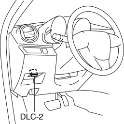
2. Connect the M-MDS (IDS) to the DLC-2.
3. After the vehicle is identified, select the following items from the initialization screen of the IDS.
a. Select “Body”.
b. Select “Restraints”.
c. Select “Passenger Seat Weight Sensor ReZero”.
4. Then, select item from the SWS Calibration screen menu in the following order.
-
Select “(1)-When you have replaced any SWS or SWS module, and/or any seat part except SWS.”
5. Perform calibration following the procedures on the M-MDS screen.
 Seat Track Position Sensor Removal/Installation [Two Step Deployment Control
System]
Seat Track Position Sensor Removal/Installation [Two Step Deployment Control
System]
1. Switch the ignition to off.
2. Disconnect the negative battery cable and wait for 1min or more..
3. Remove the front driver’s seat..
4. Remove the front seat slide adjuster..
5. Remove t ...
 Seat Weight Sensor Control Module Removal/Installation [Two Step Deployment
Control System]
Seat Weight Sensor Control Module Removal/Installation [Two Step Deployment
Control System]
CAUTION:
When the seat weight sensor control module is replaced with a new one, perform
the seat weight sensor calibration using the M–MDS..
1. Switch the ignition to off.
2. Disc ...
Other materials:
Towing
Trailer Towing
Your Mazda is not designed for towing.
Never tow a trailer with your Mazda.
Recreational Towing
An example of "recreational towing" is
towing your vehicle behind a motorhome.
The transaxle is not designed for towing
this vehicle on all 4 wheels.
When doing rec ...
Liftgate/Trunk Lid
WARNING
Never allow a person to ride in the
luggage compartment/trunk:
Allowing a person to ride in the
luggage compartment/trunk is
dangerous. The person in the luggage
compartment/trunk could be seriously
injured or killed during sudden braking
or a collision.
D ...
EGR Pipe Removal/Installation [Mzr 2.3 Disi Turbo]
1. Remove the battery cover..
2. Disconnect the negative battery cable..
3. Remove the battery and battery tray..
4. Remove the following parts..
Fresh-air duct
Air cleaner
Charge air cooler
Air hose
Air duct
5. Set the throttle body out of the way ...
