Mazda 3 Service Manual: Side Wall Removal/Installation
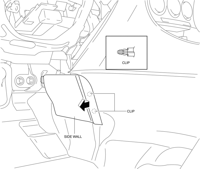
1. Pull out the side wall in the direction shown in the direction of the arrow shown in the figure, then remove the clips.

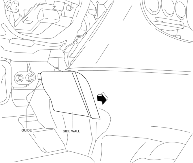
2. Remove the side wall in the direction of the arrow shown in the figure.

CAUTION:
-
When remove the side wall, be careful not to damage the guide.
3. Install in the reverse order of removal.
 Shift Panel Removal/Installation
ATX
1. Remove the upper panel..
2. Remove the selector lever knob..
3. Pull the shift panel in the direction of the arrow shown in the figure and
remove it while detaching the clips A, hook B a ...
 Trunk Side Upper Trim Removal/Installation
1. Remove the rear seat cushion..
2. Remove the rear scuff plate..
3. Remove the tire house trim..
4. Open the cap.
5. Remove the screw.
6. Remove the fasteners.
7. Pull the trunk side upp ...
Other materials:
Controller Area Network (Can) System
Outline
With the addition of the following, the system wiring diagram and CAN communication
table have been added.
USB adapter
System Wiring Diagram
CAN Signal Table
Signals transmitted using the CAN system are as follows:
MS-CANOUT: Output (send ...
Schedule 1
Chart symbols:
I: Inspect: Inspect and clean, repair, adjust, fill up, or replace if
necessary.
R: Replace
L : Lubricate
T: Tighten
Remarks:
*1 Use of FL-22 is recommended when replacing engine coolant. Using engine
coolant other than FL-22 may
cause serious damage to the engine and c ...
Auto Leveling Sensor Removal/Installation
1. Disconnect the negative battery cable..
2. Lift up the vehicle.
3. Disconnect the quick release connector. (charcoal canister side).
4. Remove in the order indicated in the table.
1
Bolt
2
Connector
3
Auto ...
