Mazda 3 Service Manual: Steering Shaft Inspection
1. Inspect the column bearing for excessive play and damage.
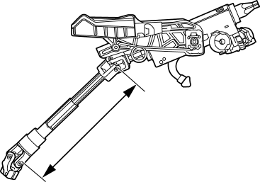
2. Verify that the measurement of the steering shaft indicated in the figure is as specified.

-
If not within the specification replace the steering shaft component.
-
Steering shaft length
-
315—320 mm {12.41—12.59 in}
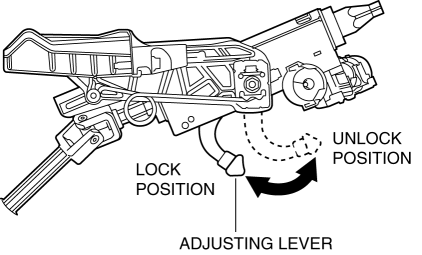
3. Inspect the tilt/telescope mechanism operation for the following.

a. Verify that the adjusting lever moves smoothly from the lock to the unlock position.
b. Verify that the steering shaft is fixed firmly when the adjusting lever is locked.
-
If there is any malfunction, replace the steering shaft.
 Wheel, Column
...
 Steering Wheel And Column Inspection
Play Inspection
1. With the wheels in the straight-ahead position, start the engine.
2. Turn the steering wheel to the left and right gently, then verify that the
steering wheel play is within th ...
Other materials:
Joint Shaft Disassembly [Skyactiv G 2.0]
1. Disassemble in the order indicated in the table.
1
Snap ring
2
Joint shaft component
.
3
Dust seal
4
Bearing
5
Dust cover
6
...
Glass Panel Adjustment
1. Fully close the glass panel.
2. Measure the gap and height between the glass panel and body.
If not as specified, loosen the glass panel installation screws and reposition
the glass panel.
Clearance (4SD)
a: -2.4—0.2 mm {-0.09—0.01 in}
b: 0 mm {0 in}
...
Supplemental Restraint System (SRS) Precautions
The front and side supplemental restraint systems (SRS) include different
types of air bags.
Please verify which kinds of air bags are equipped on your vehicle by locating
the
“SRS AIRBAG” location indicators. These indicators are visible in the area where
the air
bags are installed.
T ...
