
Mazda 3 Service Manual: Transmission/Transaxle SST
1: Mazda SST number
2: Global SST number
Example
|
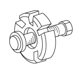
1:49 UN30 3009 2:303-009 Crankshaft damper remover |
|
Clutch [G35M-R]
|
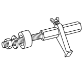
1:49 E011 1A0 2: – Ring gear brake set |
|
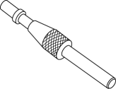
1:49 SE01 310A 2: – Clutch disc center tool |
|
1:49 1285 071 2: – Bearing puller |
|

Clutch [G66M-R]
|
1:49 E011 1A0 2: – Ring gear brake set |
|
1:49 SE01 310A 2: – Clutch disc center tool |
|
1:49 1285 071 2: – Bearing puller |
|
Clutch [A26M-R]
|
1:49 E011 1A0 2: – Ring gear brake set |
|
1:49 SE01 310A 2: – Clutch disc center tool |
|
1:49 1285 071 2: – Bearing puller |
|
|
1:49 E027 002 2: – Attachment |
|
1:49 G030 797 2: – Handle |
|
– |
|

Clutch [C66M-R]
|
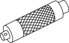
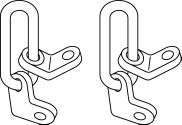
1:49 UN30 3050 2: 303-050 Engine lifting brackets |
|
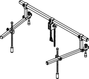
1:49 C017 5A0 2: – Engine support set |
|
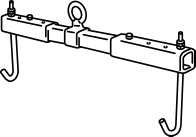
1:49 L017 5A0 2: – Support hanger |
|
|
1:49 E011 1A0 2: – Ring gear brake set |
|
1:49 SE01 310A 2: – Clutch disc center tool |
|
1:49 1285 071 2: – Bearing puller |
|
Manual Transaxle [G35M-R]
|
1:49 C017 5A0 2: – Engine support set |
|
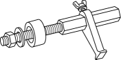
1:49 G030 795 2: – Oil seal installer |
|
– |
|
Manual Transaxle [G66M-R]
|
1:49 C017 5A0 2: – Engine support set |
|
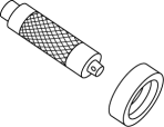
1:49 G030 796 2: – Body |
|
1:49 G030 797 2: – Handle (Part of 49 G030 795) |
|
|
1:49 M005 797 2: – Handle |
|
– |
– |
||

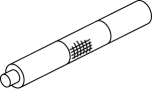
Manual Transaxle [A26M-R]
|
1:49 C017 5A0 2: – Engine support set |
|
1:49 W027 001 2: – Body |
|
1:49 F027 003 2: – Handle |
|
|
1:49 U027 003 2: – Oil Seal Installer |
|
– |
– |
||
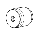
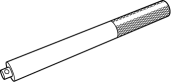

Manual Transaxle [C66M-R]
|
1:49 UN30 3050 2: 303-050 Engine lifting brackets |
|
1:49 C017 5A0 2: – Engine support set |
|
1:49 L017 5A0 2: – Support hanger |
|
|
1:49 G030 797 2: – Handle (Part of 49 G030 795) |
|
1:49 U027 003 2: – Oil Seal Installer |
|
– |
|
Automatic Transaxle [FS5A-EL]
|
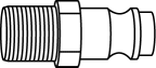
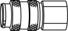
1:49 H019 002 2: – Adapter |
|
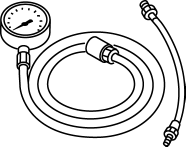
1:49 0378 400C 2: – Oil pressure gauge set |
|
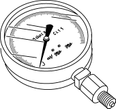
1:49 B019 901B 2: – Oil pressure gauge |
|
|
1:49 B019 902A 2: – Oil pressure gauge |
|
1:49 D019 910 2: – Adapter (Part of 49 D019 9A2) |
|
1:49 D019 911 2: – Adapter (Part of 49 D019 9A2) |
|
|
1:49 D019 913 2: – Adapter (Part of 49 D019 9A2) |
|
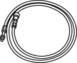
1:49 D019 909 2: – Hose (Part of 49 D019 9A2) |
|
1:49 D019 908 2: – Gauge (Part of 49 D019 9A2) |
|
|
1:49 D019 907 2: – Oil pressure gauge (Part of 49 D019 9A2) |
|
1:49 C017 5A0 2: – Engine support set |
|
1:49 E011 1A0 2: – Ring gear brake set |
|
|
1:49 G030 796 2: – Body (Part of 49 G030 795) |
|
1:49 G030 797 2: – Handle (Part of 49 G030 795) |
|
– |
|
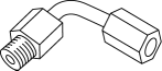
Automatic Transaxle [FW6A-EL]
|
1:49 D019 910 2: – Adapter (Part of 49 D019 9A2) |
|
1:49 D019 911 2: – Adapter (Part of 49 D019 9A2) |
|
1:49 D019 913 2: – Adapter (Part of 49 D019 9A2) |
|
|
1:49 D019 909 2: – Hose (Part of 49 D019 9A2) |
|
1:49 D019 908 2: – Gauge (Part of 49 D019 9A2) |
|
1:49 D019 907 2: – Oil pressure gauge (Part of 49 D019 9A2) |
|
|
1:49 UN30 3050 2: 303-050 Engine lifting brackets |
|
1:49 C017 5A0 2: – Engine support set |
|
1:49 L017 5A0 2: – Support hanger |
|
|
1:49 E011 1A0 2: – Ring gear brake set |
|
1:49 G030 797 2: – Handle (Part of 49 G030 795) |
|
1:49 U027 003 2: – Oil Seal Installer |
|
|
1:49 G030 796 2: – Body (Part of 49 G030 795) |
|
1:49 F027 003 2: – Handle |
|
1:49 U034 204 2: – Dust boot installer |
|
 Torque Converter Clutch (TCC) Non Operation [Fw6 A EL]
TROUBLESHOOTING ITEM
Torque converter clutch (TCC) non-operation
DESCRIPTION
TCC does not operate when vehicle reaches TCC oper ...
 Up Switch Inspection [FS5 A EL]
1. Perform the following procedures.
a. Remove the battery cover..
b. Disconnect the negative battery cable.
c. Remove the console..
d. Disconnect the selector lever component connector.
...
Other materials:
Intake Air Temperature (Iat) Sensor Inspection [Mzr 2.0, Mzr 2.5]
Resistance Inspection
NOTE:
Because the IAT sensor is integrated in the MAF sensor, replacing the IAT
sensor includes replacement of the MAF/IAT sensor.
1. Remove the battery cover..
2. Disconnect the negative battery cable..
3. Disconnect the MAF/IAT sensor connector.
4. Mea ...
Automatic Transaxle Shift Mechanism Removal/Installation
Selector Lever Removal/Installation
1. Remove the battery cover..
2. Disconnect the negative battery cable..
3. Remove in the order indicated in the table.
4. Install in the reverse order of removal.
1
Upper panel
(See UPPER PANEL REMOVAL/INSTALLATION.)
...
Quarter Window Glass Removal
1. Remove the following parts:
a. Rear seat cushion.
b. Rear scuff plate.
c. Tire house trim.
d. Trunk side upper trim.
e. C-pillar trim.
2. Apply protective tape along the edge of the body and the quarter window glass.
NOTE:
For the areas of the sealant that are difficult ...
