Mazda 3 Service Manual: Active Command Modes Inspection [Blind Spot Monitoring (Bsm)]
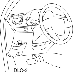
1. Connect the M-MDS (IDS) to the DLC-2.

2. After the vehicle is identified, select the following items from the initialization screen of the IDS.
a. Select “DataLogger”.
b. Select “Modules”.
c. Select “BSML” or “BSMR”.
3. Select the simulation items from the PID table.
4. Perform the active command modes function, inspect the operations for each parts.
-
If the operation of output parts cannot be verified after the active command mode inspection is performed, this could indicate the possibility of an open or short circuit, sticking, or operation malfunction in the output parts.
 Safety Systems
...
 Blind Spot Monitoring (Bsm) Bracket Removal/Installation
1. Disconnect the negative battery cable..
2. Remove the rear combination light..
3. Remove the rear bumper..
4. Remove the BSM control module..
5. Remove the nuts.
6. Remove the clip.
...
Other materials:
Glove Compartment Removal/Installation
CAUTION:
If the glove compartment is closed without being joined to the stay damper,
the stay damper may be damaged. Verify that the stay damper is joined to the
glove compartment before closing the glove compartment.
1. Pull the stay damper in the direction (1) shown in the figu ...
Saving Fuel and Protection of the
Environment
How you operate your Mazda determines
how far it will travel on a tank of fuel. Use
these suggestions to help save fuel and
reduce CO2.
Avoid long warm-ups. Once the engine
runs smoothly, begin driving.
Avoid fast starts.
Drive at lower speeds.
Anticipate when to apply the brakes
(a ...
Blind Spot Monitoring (BSM) Warning Lights/Blind Spot Monitoring (BSM)
Warning Beep
The Blind Spot Monitoring (BSM) or Rear Cross Traffic Alert (RCTA) system
notifies the
driver of the presence of vehicles in adjacent lanes to the rear of your vehicle
using the
Blind Spot Monitoring (BSM) warning lights and the warning beep while the
systems are
operational.
Blind Spot Mo ...
