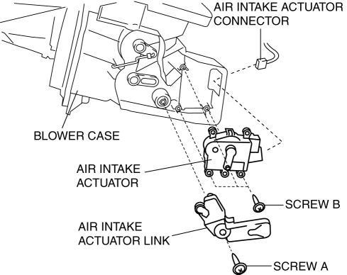
Mazda 3 Service Manual: Air Intake Actuator Removal/Installation [Full Auto Air Conditioner]
1. Set the air intake mode to FRESH.
2. Disconnect the negative battery cable..
3. Remove the following parts:
a. Front scuff plate (Passenger-side).
b. Front side trim (Passenger-side).
c. Dashboard under cover.
d. Glove compartment.
e. Lower panel (Passenger-side).
f. Shower duct (Passenger-side).
4. Disconnect the harness clip from the blower case.
5. Disconnect the air intake actuator connector.

6. Remove the blower case..
7. Remove the screw A.
8. Remove the air intake actuator link.
9. Remove the screw B.
10. Remove the air intake actuator.
11. Install in the reverse order of removal.
 Air Intake Actuator Inspection [Manual Air Conditioner]
1. Connect battery positive voltage to air intake actuator terminal B (or C),
connect terminal C (or B) to ground, and then verify that the air intake actuator
operates as shown in the table.
...
 Air Intake Actuator Removal/Installation [Manual Air Conditioner]
1. Set the air intake mode to FRESH.
2. Disconnect the negative battery cable..
3. Remove the following parts:
a. Front scuff plate (Passenger-side).
b. Front side trim (Passenger-side).
c. ...
Other materials:
Afs (Adaptive Front Lighting System) Off Switch Removal/Installation
1. Disconnect the negative battery cable..
2. Remove the switch panel in the direction of the arrow shown in the figure.
3. Disconnect the connector.
4. Remove the AFS OFF switch in the direction of the arrow (2) shown in the figure
while pressing the tabs in the direction of the arrow ...
Active Adaptive Shift (AAS)
Active Adaptive Shift (AAS)
automatically controls the transaxle shift
points to best suit the road conditions
and driver input. This improves driving
feel. The transaxle may switch to AAS
mode when driving up and down slopes,
cornering, driving at high elevations,
or depressing the accelerat ...
Headlight Bulb Removal/Installation
Halogen Type
Low-beam
1. Disconnect the negative battery cable..
2. Disconnect the connector.
3. Remove the cover.
4. Remove the adaptor.
5. Remove the headlight bulb (LO).
CAUTION:
A halogen bulb generates extremely high heat when it is illuminated. If the
surface of ...
