Mazda 3 Service Manual: Back Up Light Switch Removal/Installation [G35 M R]
1. Remove the battery cover..
2. Disconnect the negative battery cable.
3. Remove the battery component. (ex: battery, battery tray and PCM component).
4. Remove the aerodynamic under cover No.2..
5. Drain the oil from the transaxle..
6. Disconnect the back-up light switch connector and remove the back-up light switch.
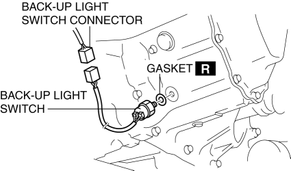
7. Install the back-up light switch (with a new gasket) to the transaxle case.
-
Tightening torque
-
20—29 N·m {2.1—2.9 kgf·m, 15—21 ft·lbf}
8. Install the battery component. (ex: battery, battery tray and PCM component)(See BATTERY REMOVAL/INSTALLATION [MZR 2.0, MZR 2.5].)
9. Install the battery cover..
10. Add the specified amount and type of oil..
11. Install the aerodynamic under cover No.2..
 Back Up Light Switch Removal/Installation [C66 M R]
1. Remove the battery cover..
2. Disconnect the negative battery cable..
3. Remove the aerodynamic under cover No.2..
4. Remove in the order indicated in the table.
5. Install in the reverse o ...
 Back Up Light Switch Removal/Installation [G66 M R]
1. Remove the battery cover..
2. Disconnect the negative battery cable.
3. Remove the battery component. (ex: battery, battery tray and PCM component).
4. Remove the aerodynamic under cover No. ...
Other materials:
DSC HU/CM Removal/Installation
WARNING:
If the DSC HU/CM configuration is not completed, it could result in an unexpected
accident due to the DSC being inoperative. If the DSC HU/CM is replaced, always
use the automatic configuration function so that the DSC operation conditions
are correct.
If the DSC se ...
Transaxle Oil Inspection [G35 M R]
1. Park the vehicle on level ground.
2. Remove the aerodynamic under cover No.2..
3. Remove the oil level plug and washer.
4. Verify that the oil is near the brim of the plug port.
If the oil level is lower than the low level, add the specified amount and
type of oil through the ...
Master Cylinder Removal/Installation [Mzr 2.0, Skyactiv G 2.0, Mzr 2.5]
1. Remove the battery and battery tray..
2. Remove in the order indicated in the table.
3. Install in the reverse order of removal.
1
Brake fluid level sensor connector
2
Reserve hose (MTX)
(See Reserve Hose (MTX) Removal Note.)
(Se ...
