Mazda 3 Service Manual: Precaution
Intermittent Concern Troubleshooting
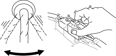
Vibration method
-
If a malfunction occurs or becomes worse while driving on a rough road or when the engine is vibrating, perform the following steps.
NOTE:
-
There are several reasons why vehicle or engine vibration could cause an electrical malfunction. Inspect the following:
-
Connectors not fully seated.
-
Wiring harnesses not having full play.
-
Wires laying across brackets or moving parts.
-
Wires routed too close to hot parts.
-
An improperly routed, improperly clamped, or loose wiring harness can cause wiring to become pinched between parts.
-
The connector joints, points of vibration, and places where wiring harness pass through the firewall, body panels and other panels are the major areas to be inspected.
Inspection method for switch and/or sensor connectors or wires
1. Connect the M-MDS to the DLC-2.
2. Switch the ignition to ON (engine off).
NOTE:
-
If the engine starts and runs, perform the following steps at idle.
3. Access PIDs for the switch you are inspecting.
4. Turn the switch on manually.
5. Slightly shake each connector or wiring harness vertically and horizontally while monitoring the PID.
-
If the PID value is unstable, inspect for poor connection.
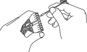
Inspection method for sensors
1. Connect the M-MDS to the DLC-2.
2. Switch the ignition to ON (engine off).
NOTE:
-
If the engine starts and runs, perform the following steps at idle.
3. Access PIDs for the switch you are inspecting.
4. Vibrate the sensor slightly with your finger.
-
If the PID value is unstable or a malfunction occurs, inspect for poor connection and/or poorly mounted sensor.
Connector terminal inspection method
1. Inspect the connection of each female terminal.
2. Insert the male terminal to the female terminal and inspect the female terminal for looseness.
 General Procedures (Steering)
Wheel and Tire Installation
1. When installing the wheels and tires, tighten the wheel nuts in a criss-cross
pattern to the following tightening torque.
Tightening torque
88—118 N· ...
 Steering SST
49 H032 301
Wrench
49 F017 1A0
Universal wrench
49 F032 303
Handle
49 B032 323
Rod seal ...
Other materials:
To Turn Off an Armed System
An armed system can be turned off using
any one of the following methods:
Pressing the unlock button on the
transmitter.
Switching the ignition ON.
(With the advanced keyless function)
Pressing a request switch on the doors.
The hazard warning lights will flash twice.
NOTE
When th ...
Windshield Wiper Motor Removal/Installation
1. Disconnect the negative battery cable..
2. Remove the following parts:
a. Windshield wiper arm and blade.
b. Front fender molding.
c. Cowl grille.
d. Center cowl grille No1, No2
3. Stick masking tape on the figure.
CAUTION:
If the front wiper motor is removed without affixin ...
Engine SST [Skyactiv G 2.0]
1: Mazda SST number
2: Global SST number
Example
1:49 UN20 5072
2:205–072
Holder
1: –
2: 134-01049A
Evaporative emission system tester
1:–
2:AKS042808
Adapter
1: 49 UN ...
