
Mazda 3 Service Manual: Knee Bolster Removal/Installation
1. Disconnect the negative battery cable..
2. Remove the following parts:
a. Driver-side front scuff plate.
b. Driver-side front side trim.
c. Hood release lever.
d. Upper panel.
e. Shift knob (MTX).
f. Selector lever knob (ATX).
g. Shift panel.
h. Side wall.
i. Console.
j. Driver-side lower panel.
3. Remove the bolts.
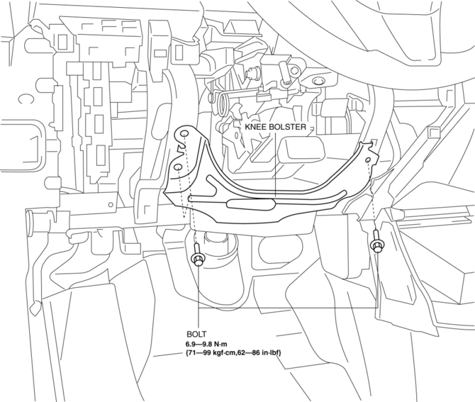
4. Remove the knee bolster.
5. Install in the reverse order of removal.
 Glove Compartment Removal/Installation
CAUTION:
If the glove compartment is closed without being joined to the stay damper,
the stay damper may be damaged. Verify that the stay damper is joined to the
glove compartment before ...
 Sunvisor Removal/Installation
1. Disconnect the negative battery cable..
2. Remove the screw.
3. Rotate the sunvisor in the direction of the arrow.
4. Unhook and remove the sunvisor.
5. Disconnect the vanity mirror ill ...
Other materials:
Rear Oil Seal Replacement [Mzr 2.0, Mzr 2.5]
1. Remove the transaxle..
2. Remove the flywheel (MTX) or the drive plate (ATX)..
3. Remove in the order indicated in the table.
4. Install in the reverse order of removal.
1
Bolt
2
Rear oil seal
(See Rear Oil Seal Installation Note. ...
Antenna Feeder No.1 Removal/Installation
1. Disconnect the negative battery cable..
2. Remove the following parts:
a. Front scuff plate.
b. Front side trim.
c. Upper panel.
d. Shift lever knob (MTX).
e. Selector lever knob (ATX).
f. Shift panel.
g. Side wall.
h. Console.
i. Shift lever component (MTX).
j. Selector lev ...
Trunk Side Trim Removal/Installation
4SD
Left-side
1. Remove the following parts:
a. Rear scuff plate.
b. Tire house trim.
c. Trunk mat.
d. Trunk board.
e. Trunk end trim.
f. Service hole cover
2. Remove the fasteners.
3. Install in the reverse order of removal.
Right-side
1. Remove the following parts:
a. Re ...
