Mazda 3 Service Manual: Lower Panel Removal/Installation
Driver-side
1. Disconnect the negative battery cable..
2. Remove the following parts:
a. Driver-side front scuff plate.
b. Driver-side front side trim.
c. Hood release lever.
d. Upper panel.
e. Shift knob (MTX).
f. Selector lever knob (ATX).
g. Shift panel.
h. Side wall.
i. Console.
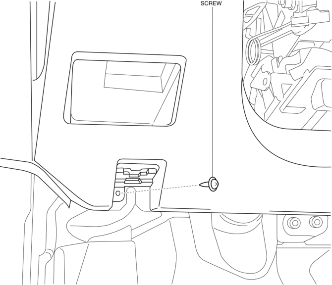
3. Partially peel back the seaming welt.
4. Remove the screw.

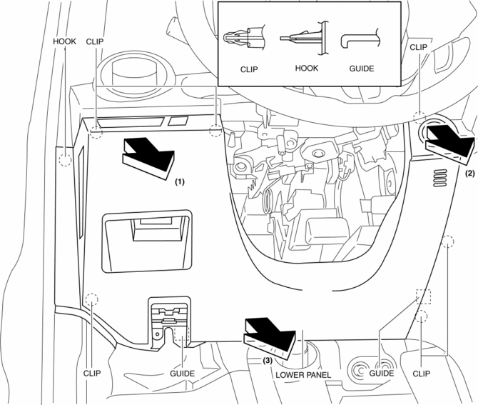
5. Pull the lower panel in the direction of the arrow in the order of (1) (2), (3) and remove the lower panel while detaching the hooks, clips and guides.

6. Disconnect the switch connector.
7. Disconnect the push button start connector.
8. Install in the reverse order of removal.
Passenger-side
1. Remove the following parts:
a. Passenger-side front scuff plate.
b. Passenger-side front side trim.
c. Dashboard under cover.
d. Glove compartment.
2. Partially peel back the seaming welt.
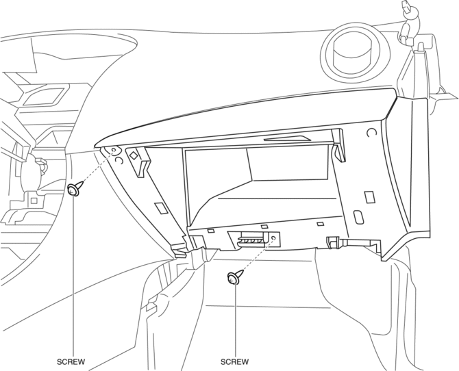
3. Remove the screws.

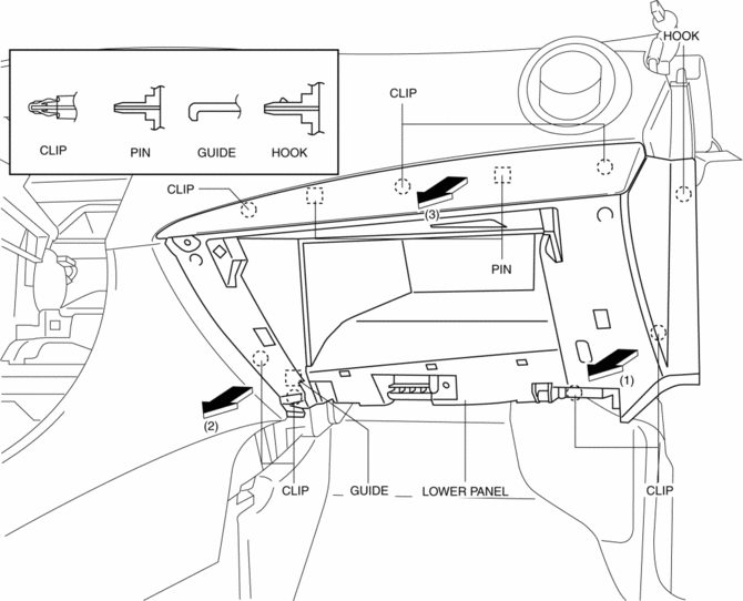
4. Pull the lower panel in the direction of the arrow in the order of (1) (2), (3) and remove the lower panel while detaching the hook, clips, guide and pins.

5. Install in the reverse order of removal.
 Inner Garnish Removal/Installation
1. Disconnect the negative battery cable..
2. Pull the inner garnish in the direction of the arrow shown in the figure and
remove it while detaching clips and tab.
CAUTION:
When pull ...
 Rear Package Trim Removal/Installation
1. Remove the following parts:
a. Rear seat cushion.
b. Rear scuff plate.
c. Tire house trim.
d. C-pillar trim.
2. Fold the rear seat back.
3. Remove the fasteners.
4. Pull up the re ...
Other materials:
Forward Obstruction Warning (FOW))
Forward Obstruction Warning (FOW) is a system which alerts the driver of a
possible
collision using an indicator and warning sound in the instrument cluster while
the vehicle
is being driven at about 15 km/h or faster (10 mph or faster) and the system's
radar sensor
determines that your veh ...
Hood Removal/Installation
WARNING:
Removing the hood without supporting it could cause the hood to fall and
cause serious injury. Always perform the procedure with at least another person
to prevent the hood from falling.
1. Disconnect the negative battery cable..
2. Remove the following parts:
a. Fro ...
Oil Seal (Differential) Replacement [G66 M R]
1. On level ground, jack up the vehicle and support it evenly on safety stands.
2. Remove the aerodynamic under cover No.2..
3. Drain the oil from the transaxle..
4. Remove the front splash shield..
5. Separate the drive shaft and joint shaft from the transaxle..
6. Remove the oil seals u ...
