Mazda 3 Service Manual: Antenna Feeder No.3 Removal/Installation
4SD (With Audio Unit (With Display))
1. Disconnect the negative battery cable..
2. Remove the rain sensor cover. (Vehicles with auto light/wiper system).
3. Disconnect the rain sensor connector. (Vehicles with auto light/wiper system)
4. Partially peel back the seaming welts.
5. Remove the following parts:
a. Sunroof seaming welt (vehicles with sunroof)
b. A-pillar trim.
c. Front scuff plate.
d. Rear scuff plate.
e. B-pillar lower trim.
f. Upper anchor of the front seat belt.
g. B-pillar upper trim.
h. Rear seat cushion.
i. Tire house trim.
j. C-pillar trim.
k. Map light.
l. Sunvisor.
m. Assist handle.
n. Headliner.
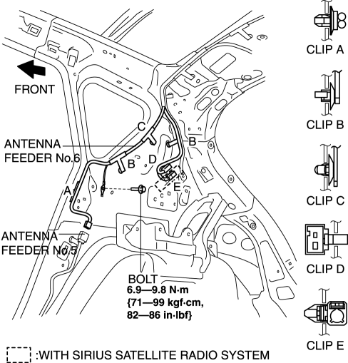
6. Disconnect the antenna feeder No.5.
7. Remove the clips A and B.
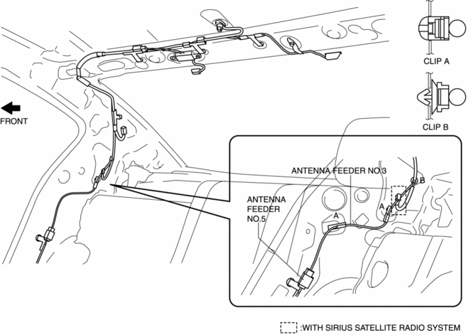
8. Disconnect the antenna amplifier connector.
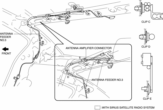
9. Remove the clips C, D and E
10. Disconnect the center roof antenna connector. (with SIRIUS satellite radio system)
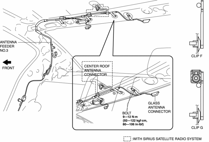
11. Disconnect the glass antenna connector..
12. Remove the bolt.
13. Remove the clips F and G.
14. Install in the reverse order of removal.
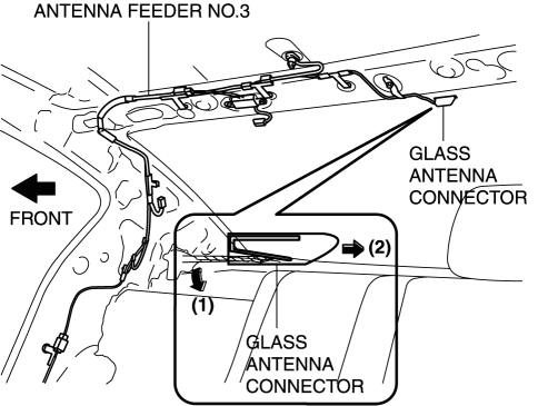
Glass Antenna Connector Removal Note
1. Remove the connector B in the direction of the arrow (2) shown in the figure while pressing the glass antenna terminal in the direction of the arrow (1).
5HB
With audio unit (without display)
1. Disconnect the negative battery cable..
2. Remove the rain sensor cover. (Vehicles with auto light/wiper system).
3. Disconnect the rain sensor connector. (Vehicles with auto light/wiper system)
4. Partially peel back the seaming welts.
5. Remove the following parts:
a. Sunroof seaming welt (vehicles with sunroof)
b. A-pillar trim.
c. Front scuff plate.
d. Rear scuff plate.
e. B-pillar lower trim.
f. Upper anchor of the front seat belt.
g. B-pillar upper trim.
h. Rear seat cushion.
i. Tire house trim.
j. Trunk side upper trim.
k. C-pillar trim.
l. Map light.
m. Sunvisor.
n. Assist handle.
o. Headliner.
6. Disconnect the connector.
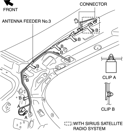
7. Remove the clips A and B.
8. Remove the antenna feeder No.3.
9. Install in the reverse order of removal.
With audio unit (with display)
1. Disconnect the negative battery cable..
2. Remove the rain sensor cover. (Vehicles with auto light/wiper system).
3. Disconnect the rain sensor connector. (Vehicles with auto light/wiper system)
4. Partially peel back the seaming welts.
5. Remove the following parts:
a. Sunroof seaming welt (vehicles with sunroof)
b. A-pillar trim.
c. Front scuff plate.
d. Rear scuff plate.
e. B-pillar lower trim.
f. Upper anchor of the front seat belt.
g. B-pillar upper trim.
h. Rear seat cushion.
i. Tire house trim.
j. Trunk side upper trim.
k. C-pillar trim.
l. Map light.
m. Sunvisor.
n. Assist handle.
o. Headliner.
p. Liftgate upper trim.
6. Disconnect the antenna feeder No.7..
7. Disconnect the antenna feeder No.5.
8. Remove the clips A, B, C, D and E.
9. Remove the bolt.
10. Disconnect the connector.
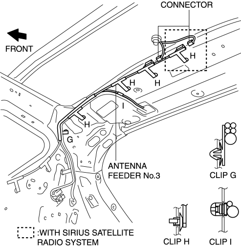
11. Remove the clips G, H, and I.
12. Remove the antenna feeder No.3.
13. Install in the reverse order of removal.
 Antenna Feeder No.3 Inspection
4SD (With Audio System (With Display))
1. Disconnect the negative battery cable..
2. Remove the rain sensor cover. (Vehicles with auto light/wiper system).
3. Disconnect the rain sensor connector ...
 Antenna Feeder No.4 Inspection
1. Disconnect the negative battery cable..
2. Remove the following parts:
a. Upper column cover.
b. Instrument cluster.
c. Center panel.
d. Audio unit (Vehicles with audio unit).
e. Center ...
Other materials:
Clock Spring Inspection [Standard Deployment Control System]
1. Disconnect the negative battery cable..
2. Remove the driver–side air bag module..
3. Remove the steering wheel..
4. Remove the column cover.
5. Remove the clock spring..
6. Verify that the continuity is as indicated in the table.
If not as indicated in the table, replace the cl ...
Driving In Flooded Area
WARNING
Dry off brakes that have become
wet by driving slowly, releasing the
accelerator pedal and lightly applying
the brakes several times until the brake
performance returns to normal:
Driving with wet brakes is dangerous.
Increased stopping distance or the
vehicle ...
Climate Control Unit Inspection [Full Auto Air Conditioner]
1. Remove the climate control unit with the connector connected..
2. Switch the ignition to ON.
3. Connect the negative (-) lead of the tester to body ground.
4. By inserting the positive (+) lead of the tester into each climate control
unit terminal, measure the voltage according to the ter ...
